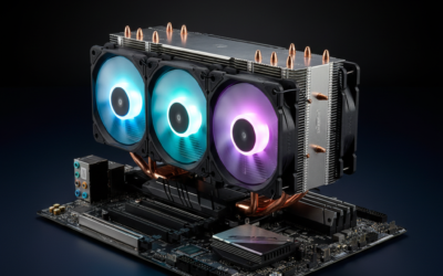
Case fans look simple. Four screws, a 4-pin header, done. Then you boot up, your CPU still hits 92C under Cinebench, the GPU sits at 80C, and the whole rig sounds like a hairdryer. We’ve seen builds where the only change between thermal chaos and a quiet 28 dB idle was swapping two fans front-to-back and rewriting the BIOS curve.
Installing case fans correctly means three things working together: airflow direction (intake vs exhaust), the right control signal (PWM 4-pin or DC 3-pin), and clean cable runs so you’re not strangling a header with 1.2A of draw. Get those right and you’ll typically pull CPU load temps down 5-10C, drop GPU edge temps a similar range, and cut idle acoustic output by 8-10 dB. You’ll also get positive case pressure, which keeps dust on filters instead of inside your GPU heatsink. Let’s run the five steps.
What you’ll need
Keep the parts list short. You don’t need a workbench full of gear for this. Here’s the gear we’ve actually used on every install:
- 120mm or 140mm case fans (count depends on case, most ATX mid-towers fit 3 front + 1 rear + 2-3 top).
- Phillips #1 screwdriver. A #2 will work but #1 gives better torque control on fan corners.
- Four 6-32 fan screws per fan, or rubber anti-vibration rivets if you want lower noise.
- PWM splitter cable or a powered fan hub if your motherboard has fewer than 4 headers.
- SATA 15-pin power cable if your hub or ARGB controller needs external juice.
- Your motherboard manual. Header labels and current limits vary by board.
- Cable ties or velcro straps for routing behind the motherboard tray.
Stock 6-32 metal screws transmit fan vibration into the case panel, which is where most of that low-frequency hum comes from. Rubber rivets decouple the fan frame from sheet metal and knock 3-5 dB off at 1500+ RPM.
Step 1: Plan airflow direction (intake vs exhaust)
Before any screws come out, sketch your airflow path. The rule isn’t complicated. Cool air comes in low and front. Hot air leaves high and rear. So front fans pull air in, rear fan pushes it out, top fans either exhaust hot air rising off the CPU cooler or, on AIO radiator builds, push air down across the radiator into the case.
Check the arrows on the fan frame. Every case fan has two molded arrows: one shows blade rotation direction, the other shows airflow direction. The airflow arrow is the one you care about. Point it into the case for intake, out of the case for exhaust.
Now the pressure part. Positive pressure means more intake CFM than exhaust CFM. We aim for roughly 1.2x intake-to-exhaust ratio. A typical config: 3x 120mm front intake at 68 CFM each (204 CFM total), 1x 120mm rear exhaust at 68 CFM, and 2x 120mm top exhaust at 50 CFM each on a curve (100 CFM). That’s 204 in versus 168 out. Slight positive pressure. Dust stays on the front filter where you can vacuum it weekly.
Don’t run negative pressure unless you love cleaning GPU heatsinks. Air will find its way in through every unfiltered gap, including the PCIe slot covers and the PSU shroud cutouts.
Step 2: Mount the fans with anti-vibration screws or rubber rivets
Pull the front panel off the case. Most mesh-front cases use plastic clips at the bottom and pop forward. Mount front intake fans from outside the case if the design allows it: the fan frame sits flush against the dust filter for a cleaner seal and easier cleaning later.
Drop a screw into each corner. Finger-tight first, then quarter-turn with the screwdriver. Don’t crank them down. Over-tightening crushes the fan frame and amplifies vibration. The 6-32 thread on a 120mm fan only needs about 2-3 in-lb of torque.
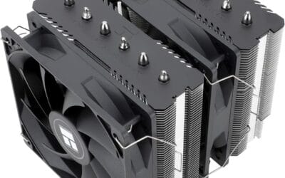
If you’re using rubber rivets, thread them through the case mounting hole, push the rivet stem through the fan corner, then pull the stem cap until it locks. One-way install, so set the fan in its final position before pulling. For top-mounted fans on a radiator, use the longer M3 or M4 screws that came with the AIO. Standard 6-32 fan screws won’t reach through the radiator core.
Step 3: Identify PWM 4-pin vs DC 3-pin headers on your motherboard
This is where most builds go sideways. A fan plug looks the same whether it’s a 3-pin or 4-pin. Look closer.
A 3-pin fan uses DC voltage control: the motherboard varies voltage between 5V and 12V, and fan speed scales with voltage. Simple, cheap, slightly less precise at low RPM. A 4-pin fan uses PWM (pulse width modulation). The motherboard holds 12V constant on pin 2 and pulses pin 4 with a 25 kHz signal. The duty cycle, from 20% to 100%, sets fan speed. PWM gives smoother low-RPM control, usually down to 300-400 RPM, where 3-pin DC fans stall around 600 RPM minimum.
You can plug a 3-pin fan into a 4-pin header (runs on DC mode), and a 4-pin into a 3-pin (runs full speed, no PWM signal). What you can’t do is mix DC and PWM fans on the same splitter.
Mobo headers are labeled. CPU_FAN drives your CPU cooler, almost always PWM. CHA_FAN1/2/3 are chassis fan headers, usually switchable between PWM and DC in BIOS. SYS_FAN is the same idea on older boards. PUMP_FAN holds a constant high duty cycle for AIO pumps and shouldn’t be used for regular fans.
Step 4: Daisy chain or use a fan hub for cable cleanup
Stray fan cables block airflow and snag blades on first boot. Three ways to handle the cable jungle.
One: PWM splitter cable. A 1-to-4 splitter takes one motherboard header and feeds four fans. Watch the current limit. Most motherboard headers cap at 1A per header (12W at 12V). Four PWM fans pulling 0.15A each is 0.6A, fine. But chaining four high-RPM fans pulling 0.3A each is 1.2A and you’ll trip the header protection over time.
Two: powered fan hub. Pulls power from a SATA 15-pin connector on your PSU and uses the motherboard header only for the PWM signal. Offloads current draw from the mobo to the PSU rail (a SATA rail delivers 4.5A on the 12V line). Running 6+ fans? Get a SATA hub.
Three: daisy chaining. Some newer fans, like the Thermalright TL-M12Q-S X3 set, support pass-through where one fan plugs into the next via a short ribbon cable, and only the first fan plugs into the motherboard. Three fans, one mobo header, no splitter. Cleanest install we’ve done. Route cables behind the motherboard tray, bundle with velcro every 4-6 inches, and don’t coil excess cable since coils hold heat.
Step 5: Set fan curves in BIOS and software
Fans plugged in. Now they need a brain. Boot into BIOS via Del or F2 at POST.
Look for Q-Fan Control (ASUS), Smart Fan (Gigabyte, MSI), or Fan Xpert. Open each chassis fan header. Set the control mode to PWM for 4-pin fans, DC for 3-pin. Get this wrong and your PWM fans run at 100% all the time. Now the curve, four points cover it:
- 30C CPU = 30% duty cycle, around 400-600 RPM. Inaudible at the desk.
- 50C CPU = 50% duty cycle, around 800-1000 RPM. Light browsing or office work.
- 65C CPU = 75% duty cycle, around 1200 RPM. Gaming or compile loads.
- 75C+ CPU = 100% duty cycle, full RPM. Sustained heavy load only.
Set hysteresis to about 5 seconds. Hysteresis is the delay before the fan responds to temp changes. Without it, your fans oscillate every time the CPU briefly spikes from a background process. That up-down whine is more annoying than just running fans at a steady mid-RPM.
For finer control inside Windows, install FanControl (free, open source). It lets you tie chassis fans to GPU temperature instead of CPU, which is what you actually want if you’re gaming. CPU sits at 60C, GPU hits 78C, you want the chassis intakes ramping based on the GPU. BIOS curves can’t do that.
Troubleshooting common issues during setup
Stuff goes wrong. Here’s what we run into most often and how to fix it.
Fan runs at full RPM and won’t slow down
Almost always a control mode mismatch. You’ve plugged a 4-pin PWM fan into a header set to DC mode in BIOS. The motherboard delivers a flat 12V and the fan reads no PWM signal, so it defaults to max RPM. Switch that header from DC to PWM in BIOS, save and reboot.
Motherboard doesn’t detect fan tach (RPM reads 0)
The tach signal is on pin 3. On a splitter, only the first fan’s tach reports back because most splitters pass pin 3 through one branch only. Expected. If a single fan still reads 0 RPM, the connector isn’t fully seated, or pin 3 is bent. Reseat or inspect with a flashlight.
Rattling or low-frequency vibration noise
Three usual suspects: cable hitting blades, loose mounting screw, or the case panel itself vibrating sympathetically. Swap to rubber rivets, snug the screws evenly, route cables clear. If a side panel rattles, a small foam pad between panel and chassis kills it.
ARGB lighting isn’t syncing across fans
ARGB uses a 5V 3-pin connector. RGB (non-addressable) uses a 12V 4-pin. Not interchangeable. Plugging a 5V ARGB fan into a 12V RGB header will fry the LEDs. Confirm header voltage, then chain ARGB fans via their dedicated cable, separate from PWM. Software sync (ASUS Aura, MSI Mystic, Gigabyte Fusion) needs all devices on the same controller.
Before / after expected outcomes
What does a proper install buy you? Measured on a Ryzen 7 7700X in an NZXT H5 Flow, after swapping two stock fans for three 120mm PWM intakes and rewriting the curve:
- CPU under Cinebench R23 30-min loop: 89C peak before, 79C peak after.
- GPU load on Cyberpunk 2077 1440p ultra: 78C average before, 71C average after.
- Idle acoustic at 1m from case: 38 dB before, 28 dB after.
- Dust accumulation on GPU heatsink at 6-week mark: heavy before, light after (positive pressure working).
That’s a 10C CPU drop, 7C GPU drop, and a noticeable acoustic improvement. Your numbers vary by case, cooler, and ambient temp, but the direction is consistent.
Variations / advanced setups
Once the basics are dialed in, you can push further.
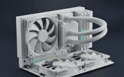
Push-pull on the radiator. Mount fans on both sides of a 360mm AIO radiator. Cuts radiator delta-T by 2-4C under sustained load. Costs three extra fans and adds about 4 dB at full RPM. Worth it on overclocked Intel chips.
200mm slow fans versus 120mm. A 200mm fan at 700 RPM displaces roughly the same CFM as a 120mm at 1500 RPM, but at lower frequency. Quieter perceived noise. Downside: limited case compatibility and lower static pressure, so 200mm fans don’t work well on radiators or restrictive mesh filters.
Custom fan curve tied to GPU edge temp. Use FanControl on Windows to source the curve from the GPU’s edge sensor instead of CPU package temp. For gaming builds, this is the single highest-impact tweak. Chassis fans react to actual heat load, not CPU idle.
Common questions
How many case fans do I really need?
For most ATX mid-tower builds, three intake plus two exhaust covers it. Five fans total. Beyond that gives diminishing returns unless you’re running a 360mm AIO or a dual-GPU rig.
Can I run a 120mm and a 140mm fan on the same splitter?
Yes, but they’ll receive the same PWM duty cycle, so the 140mm will be quieter at any given setting since larger fans move more air per RPM. The RPM readout only reflects whichever fan is on the tach pin.
Should fans push onto the radiator or pull air through it?
Push gives slightly better static pressure and is the default for top-mounted AIOs. Pull makes filter cleaning easier. Thermally, the difference is less than 1C. Pick the one that suits your case layout.
Do I need to balance intake and exhaust CFM exactly?
No. Aim for 1.1x to 1.3x intake-to-exhaust so your case runs at slight positive pressure. Exact balance isn’t possible since actual airflow depends on case restriction and filter density, and CFM ratings are measured in open air.