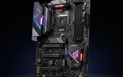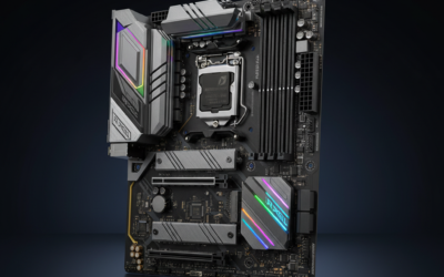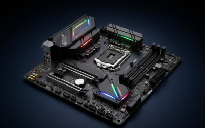

Updating BIOS used to be terrifying. A power blip mid-flash bricked the board, and the fix meant mailing it back. Modern boards ship with BIOS Flashback, dual firmware chips, and crash recovery that make the process safer than a clean Windows install. The rules still matter though. Wrong file, interrupted write, or a skipped compatibility prompt can still kill a motherboard.
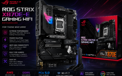
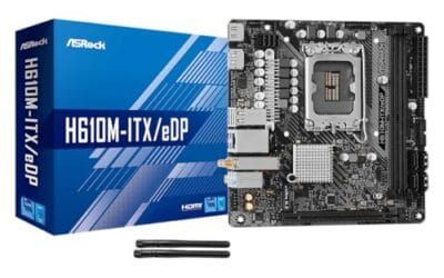
Here’s the safe sequence for ASUS, MSI, Gigabyte, and ASRock boards in 2026, including what the no-CPU flash modes actually require and what happens when a write dies halfway. The flash itself takes 60 to 180 seconds. Prep eats the time, and prep is where nearly every bricked-board story starts. On a compact ASUS Mini-ITX build the flashback button matters more, since there’s rarely a spare CPU around to POST with.
Gear and prep before you touch anything
A USB drive between 4 GB and 32 GB, formatted FAT32. ASUS and MSI boards reject NTFS drives at the flashback stage, and that isn’t a bug. Flash routines lean on FAT because the UEFI specification requires FAT support for the EFI system partition, so it’s the one filesystem every board’s ROM reads without a driver. Boards also refuse drives above 32 GB even if you shrink the partition, since the controller reads total device capacity. Owner reports indicate high-speed USB 3.2 sticks sometimes fail to negotiate on flashback ports.
The board maker’s own site is the only safe source. Skip forum mirrors and “BIOS mod” repacks, because a tampered image can lock the chip permanently. Find your exact model on the PCB silkscreen, something like PRIME B650-PLUS or MAG B550M MORTAR WIFI, then match the revision. A Rev 1.0 and a Rev 1.1 can take different images.
A stable power source. A UPS if your grid flickers, a plugged-in charger on a laptop. Don’t flash with a Windows Update restart pending, because a scheduled reboot can cut the chip off mid-write.
One thing catches people out: if your system drive is encrypted with BitLocker, new firmware changes the TPM measurements and Windows can demand the 48-digit recovery key on the next boot. Save it off the machine first. Custom Secure Boot keys get cleared too.
Step 1: Pin down the exact board and firmware version
Open Run with Win+R and type msinfo32. System Summary lists BaseBoard Manufacturer, BaseBoard Product, and BIOS Version/Date. Write down all three. If the installed build is over 18 months old and a recent CPU isn’t booting cleanly, an update is probably warranted. If the machine already works, name the thing you’re fixing. Newer isn’t automatically better with firmware.
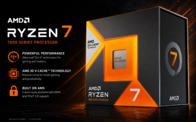
The legitimate reasons are narrow: a CPU newer than the board shipped to support, an AGESA revision that adds that support, a memory compatibility fix for a specific kit, a security advisory covering your chipset, or a changelog line naming your exact symptom. Socket AM5 is the clearest case, since AMD’s Ryzen desktop lineup has spanned several generations on one socket, and a board built for the first wave needs new microcode before it will POST with a later chip. Read the changelog before you download.
Pros
- Compact three-step structure is easier to follow mid-flash than a full PC repair manual
- Kindle Edition means no physical shipping and instant access when troubleshooting a boot issue
- Targets a specific task rather than trying to cover general PC building end to end
Cons
- Limited owner feedback at time of writing makes content quality hard to verify before buying
- Vendor BIOS Flashback and Q-Flash procedures differ by board, generic three-step guides can miss ASUS, MSI, and Gigabyte specifics
- Page count, publish date, and coverage of UEFI vs legacy BIOS are not specified in listing data
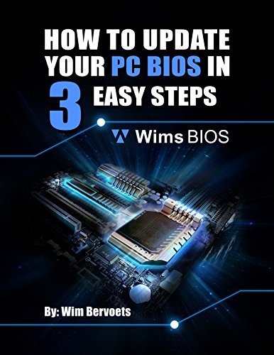
This is a short Kindle eBook by Wim Bervoets covering the process of updating a desktop PC BIOS in three sequential steps. It sits in the beginner reference tier rather than the deep-dive technical manual tier, and is aimed at first-time builders or casual upgraders who want a focused walkthrough before touching their motherboard firmware.
The defining feature is scope discipline: rather than bundling BIOS updates into a broader PC maintenance book, the title stays on one task. For a reader who has just swapped a Ryzen CPU onto an older AM5 board or is preparing for a chipset AGESA update, a task-scoped guide is easier to follow than a general repair manual. Depth of coverage per vendor is not specified in the listing.
Trade-offs are typical of self-published niche guides. BIOS update procedures diverge sharply between ASUS EZ Flash, MSI M-Flash, Gigabyte Q-Flash, and ASRock Instant Flash, and a three-step framework will not capture every UI. Page count, edition date, and whether BIOS Flashback without a CPU is covered are all absent from the listing data, and owner reviews are not yet available to confirm accuracy.
Buy this if you are a first-time builder who wants a cheap, focused primer before flashing your board and prefers a Kindle reference open on a second screen. Skip this if you already use vendor documentation, run enthusiast forums like r/buildapc, or need coverage of server-class BMC and IPMI firmware updates.
Format: Kindle eBook, delivered as a Kindle Edition digital purchase rather than a paperback or hardcover. Requires a Kindle device, the Kindle app on iOS or Android, or Kindle for PC to read, which matters if you plan to reference it during a flash and cannot use the same PC that is being updated.
Product group: Listed under Digital Ebook Purchas in the Amazon catalog, meaning no physical shipping, no returns window for used condition, and instant download after purchase. Useful when a failed boot is blocking access to a desktop and a tablet or phone is the only working device.
Author and scope: Authored by Wim Bervoets and titled around three sequential steps for updating a PC BIOS. Depth per motherboard vendor, coverage of UEFI vs legacy BIOS modes, and treatment of features like BIOS Flashback without a CPU installed are not specified in the source listing.
Not specified: Page count, publication date, edition revision, table of contents, and whether the guide addresses AM4, AM5, LGA1700, or LGA1851 platforms specifically are all absent from the provided data. Buyers who need vendor-specific procedures should confirm via the Look Inside preview before purchase.
Step 2: Get the file from the maker, not a mirror
Go to the support page for your specific board, not the chipset family page. ASUS lists every model in its motherboard catalog, then it’s Support, Driver & Utility, BIOS & Firmware. MSI: msi.com/Motherboard, search the model, Support tab. Gigabyte: gigabyte.com/Motherboard, model page, Support, BIOS. ASRock: asrock.com/mb, model, Support, BIOS.
Take the newest stable release and skip betas unless one names the fix you need. Extensions vary. ASUS ships .CAP files, MSI uses numbered extensions in the .B50 style, Gigabyte uses .F-numbered files like Z790.F12, ASRock uses .ROM or a bare number. Many downloads arrive zipped, so extract first, then check the file size against the figure on the download page.
Step 3: Format, copy, and rename if flashback is the plan
Format the stick as FAT32. Right-click the drive in File Explorer, Format, FAT32, Quick Format checked, Start. Copy the image to the root of the drive. Not a subfolder.
Filenames only matter for the no-CPU modes. ASUS EZ Flash reads any name from inside the firmware interface, but USB BIOS Flashback wants a board-specific name the manual spells out, usually the model with spaces stripped. MSI expects MSI.ROM on most boards. Gigabyte’s Q-Flash Plus wants GIGABYTE.BIN. ASRock takes the file as downloaded. Check your manual’s flashback page for the exact string, because a wrong name means the controller never sees a valid image and the LED blinks indefinitely.

Pros
- Bundled kit includes CH341A, SOIC8 clip, 1.8V adapter, and SOIC8 to DIP8 adapter
- 3.3V and 5V switching covers most 24CX EPROM and 25CXX SPI flash targets
- Works with common tools like CH341A Programmer software, flashrom, and AsProgrammer
Cons
- Limited owner feedback at time of writing makes long-term reliability hard to verify
- No native 1.8V rail on the CH341A itself, low-voltage chips require the included adapter
- User manual is not shipped in-box, buyer must request it from the seller via Ask a Question
This is an entry-level CH341A USB programer kit aimed at PC hobbyists, repair technicians, and router moders who need to read, erase, and rewrite 24 series EEPROM and 25 series SPI flash chips. The bundle targets BIOS recovery on bricked motherboards, laptop EC reflashing, and firmware dumps on embedded devices.
The defining feature is the complete accessory set in one box. The SOIC8 clip with beryllium copper pins allows in-circuit reads without desoldering, while the SOIC8 to DIP8 adapter handles loose chips on the bench. The 1.8V adapter is the key inclusion, as bare CH341A boards only switch between 3.3V and 5V and will damage low-voltage flash.
Trade-offs are typical at this tier. The CH341A design is well documented but known to output slightly over 3.3V on some clones, which can stress sensitive chips over long sessions. The SOIC8 clip is functional for occasional use but contact pressure degrades with repeated clamping. No printed manual ships in the box, which is friction for first-time users.
Buy this if you need a cheap, tool-suported programer for 24/25 series chips and are comfortable pairing it with flashrom, AsProgrammer, or NeoProgrammer. Skip this if you need to flash 1.2V chips, high-density parallel NOR, or require a waranted lab-grade tool like the RT809H or XGecu T56.
Programer core: Based on the WCH CH341A USB to serial bridge, exposing SPI and I2C modes for flash and EEPROM access. Supports 24CXX I2C EEPROM and 25CXX SPI NOR flash families, with 3.3V and 5V logic switching selectable on the board.
Voltage support: Native 3.3V and 5V only on the CH341A. The included 1.8V adapter board level-shifts signals for low-voltage SPI flash common in modern ultrabooks, some routers, and newer chipset BIOS chips. AITRIP explicitly warns to confirm chip voltage before clping to avoid burning the die.
Included adapters: SOIC8/SOP8 test clip with beryllium copper plated needles for in-circuit programing, a SOIC8 to DIP8 socket adapter for loose chips, and the 1.8V level-shift board. Clip pitch matches standard SOIC8 and SOP8 packages, no soldering required.
Software compatibility: Works with the stock CH341A Programmer utility on Windows and with flashrom on Linux and macOS via thech341a_spi driver. Also compatible with AsProgrammer and NeoProgrammer for expanded chip databases beyond the vendor tool.
What Flashback, Q-Flash Plus, and M-Flash actually require
These names get thrown around interchangeably and they aren’t the same feature.
M-Flash on MSI, EZ Flash 3 on ASUS, Q-Flash on Gigabyte, and Instant Flash on ASRock all run from inside the firmware interface. Each needs a board that POSTs, a working CPU, and one stick of RAM. They read the image off USB, verify it against the board ID, then write. That’s the normal path.
USB BIOS Flashback on ASUS, Q-Flash Plus on Gigabyte, Flash BIOS Button on MSI, and BIOS Flashback on ASRock work differently. A small embedded controller handles the write independently of the CPU, so these run with no processor, no memory, and no graphics installed. The requirements are rigid: the 24-pin ATX and CPU 8-pin EPS connectors both seated, the PSU switch on, the system powered off throughout. The stick goes in one specific rear port marked on the I/O shroud. Not any port.
Not every board has it, which is what people discover too late. On ASUS it’s generally a ROG, Strix, and upper-tier TUF feature, while budget PRIME and A-series boards ship without. MSI’s cheaper B-series often omits the button as well. Look for a small recessed button on the rear I/O labeled BIOS or FlashBK before you plan around it. If it isn’t there and the board won’t POST with a new CPU, you’ll need to borrow a supported one.
Step 4: Flash from inside the firmware if the board still boots
Take this route whenever the board POSTs. Reboot, press Del on most boards or F2 on several Gigabyte models, then find the utility: EZ Flash 3 on ASUS, M-Flash on MSI, Q-Flash on Gigabyte, Instant Flash on ASRock. What you’re launching is a routine baked into the firmware image itself, part of why the term BIOS stuck around long after the underlying code stopped being one.
Point the utility at the USB drive and select the file. It checks the image against the board ID and warns if the pairing is wrong. If it says the image may not be compatible, back out and re-check the download. If it passes, start the write and walk away. The board reboots itself one to three times. Don’t touch the case, don’t power cycle, don’t move it. When POST returns, enter setup, load optimized defaults with F5, save and exit.
Step 5: Flashback when the board won’t POST
Dead board, a new CPU with no microcode, or a previous flash that failed partway. That’s what flashback exists for. If yours can’t reach setup for reasons unrelated to firmware, work through the no-POST checklist first, because writing a good image won’t fix a shorted standoff or a dead PSU.
Power off and unplug. Insert the stick into the dedicated flashback port. Connect only the 24-pin and the CPU 8-pin, nothing else. Plug the PSU back in, flip its switch on, leave the system off. Press and hold the flashback button for 3 seconds until the dedicated LED starts blinking, then release. The LED blinks for 3 to 8 minutes. Solid or off means finished. Kill the PSU switch for 30 seconds, reconnect everything, and POST normally. A fast strobe rather than a steady blink means the file wasn’t recognized, nearly always a naming or format problem.
Confirm the flash actually landed
Enter setup and read the version string. It should match the file you flashed, not the build you started with, and msinfo32 gives a second opinion from outside the firmware. Run something sustained afterward, Cinebench R23 for 15 minutes is enough, to shake out microcode or memory-training problems.
Every flash wipes your settings, so XMP and EXPO profiles, fan curves, boot order, and voltage offsets all revert to defaults. Re-enable the memory profile first, since sitting at the 4800 MT/s JEDEC fallback instead of a rated 6000 MT/s is the most common post-update complaint and it’s silent. Once stable, confirm the profile is genuinely active and save the working configuration into a BIOS profile slot.
What a failed flash actually looks like
An interrupted write doesn’t automatically brick a board. The outcome depends on what recovery hardware it carries.
Single-chip boards with no backup are the bad case. The chip holds a partial image, nothing POSTs, and no button will help. Recovery means rewriting the SPI chip directly with a CH341A programmer and a clip, or paying a shop somewhere in the 40 to 80 dollar range. Dual-BIOS boards are kinder. Gigabyte uses them widely, as do higher-end ASUS and MSI models, and the second chip takes over automatically or after a few failed POST attempts, letting you rewrite the primary from the known-good copy. Boards with a flashback controller are usually recoverable even on a single chip, since that controller writes the ROM without a working CPU. That’s the real value of the feature.
Worth knowing first: a failed flash isn’t always a warranty matter. Several makers treat a chip bricked by a user-initiated update as a chargeable repair rather than an RMA, and that stance firms up if the image was a beta.
When leaving the firmware alone is the right call
Plenty of releases are worth skipping.
If the machine is stable, the CPU is one the board shipped to support, and the changelog only lists compatibility for hardware you don’t own, that release has nothing in it for you. Firmware revisions introduce bugs about as often as they remove them. Fan curves shift, USB controllers drop out under load, memory training turns slower or starts failing on kits that ran fine for a year. Skip it the night before you need the machine working.
Keep expectations honest about what a flash can do, too. New firmware can enable a newer CPU, add memory profiles, and patch microcode. It can’t add PCIe lanes, change a slot’s generation, or raise what the VRM delivers.
Mistakes that actually brick boards
Flashing from a Windows utility tops the list. A few Gigabyte and ASRock boards still ship an app for it, and it usually works, but Windows can hang, a driver can fault, or an update can force a restart mid-write.
The rest of the list is short and boring. Clicking past the compatibility warning because you’re impatient. Flashing a file meant for the other revision of your board. Pulling the stick during the reboot cycle on the assumption the write had finished. Updating firmware to chase a stutter you haven’t diagnosed, which often turns one problem into two.
Common questions
How long should I wait before assuming a flash has failed?
Longer than feels comfortable. An in-firmware write runs 60 to 180 seconds and flashback runs 3 to 8 minutes, but that’s not the end of it. Many boards then spend 30 to 60 seconds on memory training at first POST with a blank screen, and DDR5 training on a four-stick kit can push past two minutes. Give it 15 minutes of no LED change and no fan change before you reach for the power switch.
Do I need to clear CMOS after updating?
Most boards handle it as part of the flash. If you hit boot problems afterward, clear it manually, either with the jumper or button the manual points to, or by pulling the CR2032 battery for 5 minutes with the PSU unplugged. Do that before concluding the flash went wrong.
Can I roll back to an older version?
Usually, unless the maker has locked it. Intel-based boards sometimes refuse to go back past a microcode revision tied to a security fix, and that block isn’t something the flash utility will let you argue with. AMD boards generally allow movement in both directions, though dropping below the AGESA version your CPU needs leaves you with a board that won’t POST.
Does a BIOS update erase Windows or my drives?
No. The firmware lives on its own SPI chip and the write never touches storage. Two things still make it feel that way. Boot order resets, so the machine may try a secondary drive and hand you an error instead of Windows. And if the storage controller mode reverts from RAID or Intel VMD to AHCI, Windows can’t find the volume it was installed against. Set the mode back and it boots as normal.
How often is worth updating?
Once a year covers most people, and zero times a year is fine on a stable machine that isn’t changing hardware. Move sooner for a CPU the board didn’t originally support, or for a security advisory naming your chipset. Don’t chase monthly releases.