

An EZ Debug CPU light usually means the motherboard stopped during CPU initialization. The board powered up far enough to check the processor, but it did not get a clean handoff from the CPU, socket, EPS power, memory training, or BIOS support layer. Annoying. The good news is that a CPU LED does not always mean the processor is dead. It often points to a power lead that is not fully seated, a cooler mounting issue, a bent LGA pin, or a BIOS mismatch after a CPU upgrade. If you are planning a rebuild around AM5 or LGA1700, our guides to the best motherboard for 9800X3D, best 7800X3D motherboard, and best motherboard for i7-14700K are useful context, but this guide is about getting the system in front of you to POST first.
First check the obvious (the 30-second check)
Start with the simplest failure points before pulling the cooler or blaming the chip. Shut the PC down, switch the PSU off, and unplug the wall cable. Press the case power button for a few seconds to drain standby power. Then reseat the 24-pin motherboard cable and the CPU EPS cable near the top-left of the board. Many boards use one 8-pin EPS connector, while higher-end models may add a second 4-pin or 8-pin. The main 8-pin needs to click in cleanly. A PCIe 8-pin cable can look similar, but it is not the same cable, and forcing the wrong lead can keep the board from starting correctly. Related buying context: best motherboard for i9 13900k, and best motherboard for i9 13900k 2.
Next, boot with the minimum hardware: motherboard, CPU, CPU cooler, one memory stick, and the graphics card only if the CPU has no integrated graphics. Remove extra drives, USB hubs, RGB controllers, and front-panel accessories. Use the board’s power pins or the case power switch, then watch the debug LEDs in order. If the CPU light turns on and stays on, do not keep power-cycling the machine for ten minutes. Stop. One or two careful attempts are enough. Repeated failed starts with an incorrectly mounted cooler or a short under the board can turn a small problem into a bigger one.
Cause #1: EPS CPU power is loose, wrong, or split incorrectly
The CPU LED can light when the processor is fine but the VRM never receives stable power. This is common after a PSU swap, cable-management session, or case move. Check the cable labeled CPU, EPS, or 4+4 CPU at the PSU end and the motherboard end. On modular PSUs, do not mix cables from another power supply, even if the connector fits. Pinouts can differ between brands and even between series. That tiny shortcut saves time until it doesn’t.
A 4+4 CPU cable should join into an 8-pin block before it goes into the motherboard. If only half is connected on a board that expects the full 8-pin, the system may spin fans but hang on CPU initialization. Also inspect the latch. If the latch is not over the socket tab, the cable can sit one millimeter high and still look connected from above. For boards with an extra CPU power socket, the primary 8-pin is the one that matters first. The auxiliary connector is usually for high-current CPUs or overclocking headroom, not basic startup on a stock chip.
Cause #2: Cooler pressure or socket contact is wrong
A CPU needs even contact with the socket and cooler hardware. If the cooler is overtightened on one corner, mounted with the wrong standoffs, or sitting on a plastic protective film, the board may halt with a CPU light before you ever see a display signal. This is especially relevant after an air-cooler or AIO swap. Remove power, loosen the cooler in a cross pattern, and check that the backplate, standoffs, brackets, and screws match the socket. LGA1700, AM4, and AM5 hardware can look close enough to confuse, but a few millimeters of height difference changes mounting pressure.
If the machine started once and then stopped after you tightened the cooler, suspect pressure before suspecting the processor. For Intel LGA sockets, remove the CPU and inspect the socket under bright light. Bent pins can cause a CPU LED immediately because the board cannot read the CPU correctly. For AMD AM4 chips, inspect the CPU pins instead. AM5 moved the pins to the socket, so treat it more like Intel. Use patience here. No metal picks, no scraping, no aggressive cleaning. If you see thermal paste inside the socket, that is a serious contamination issue and it may need professional cleaning or board replacement.
Cause #3: BIOS support does not match the CPU
A motherboard can physically accept a processor and still fail at the CPU light if the installed BIOS is too old. This is a classic issue on boards that support several CPU generations. An LGA1700 board may need a newer BIOS for some 13th or 14th Gen Intel Core processors. An AM4 board may need a newer BIOS for later Ryzen chips. The box label can help, but it is not proof. Retail inventory sits on shelves, and the BIOS version on the board is whatever was flashed at the factory or by a previous owner.
Look for a BIOS Flashback, Q-Flash Plus, Flash BIOS Button, or similar feature. If the board has it, you can often update the BIOS with a USB stick, PSU power, and no working CPU boot. Follow the motherboard manual exactly for USB formatting, file naming, and the correct rear USB port. If the board does not have a no-CPU flash feature, you may need an older compatible CPU, a local shop, or a replacement board that lists support for your processor generation out of the box. We’ve seen this misread as a dead CPU many times in owner reports. It isn’t glamorous, but firmware support matters.
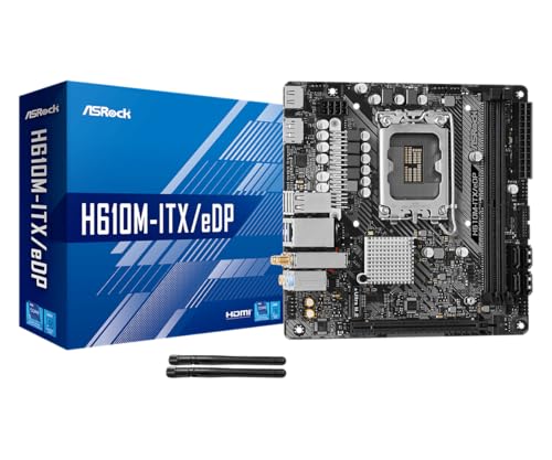
If your Intel Mini-ITX board is the part that failed, the ASRock H610M-ITX/eDP is a compact LGA1700 replacement option at $89.99 with a 4-star rating. Its title lists support for Intel 14th, 13th, and 12th Gen Core processors, DDR4, PCIe 4.0, HDMI, DisplayPort, Intel Gigabit LAN, Wi-Fi 5, and Dr.MOS power hardware. That makes it relevant when the fix is replacing a damaged or incompatible small-form-factor Intel board rather than replacing the CPU itself.
Pros
- eDP 1.4 header is rare at this tier, ideal for custom AIO and panel builds
- Dr.MOS 50A 6-phase VRM adequate for 65W LGA1700 CPUs in SFF cases
- PCIe 4.0 x16 slot preserves GPU bandwidth despite H610 chipset limits
- Integrated WiFi 5 and Bluetooth 5.1 plus Intel Gigabit LAN cover connectivity
Cons
- Limited owner fedback available at time of writing, making reliability signal thin
- H610 blocks CPU overclocking and caps DR4 at 3200MHz with no XMP scaling
- Single M.2 slot is Gen3 x4 only, no Gen4 NVMe or secondary M.2
The ASRock H610M-ITX/eDP is a budget LGA1700 Mini-ITX board built around Intel's entry H610 chipset with DDR4 memory and a dedicated eDP 1.4 panel connector. It targets SFF builders, embedded system integrators, and digital signage projects rather than gamers chasing K-series CPUs or high-frequency RAM tuning.
The standout is the eDP 1.4 header, which lets integrators drive a laptop-style FHD 60Hz panel directly, useful for all-in-one and industrial builds. For general desktop use, HDMI 2.1 outputs 4K 60Hz and DisplayPort 1.4 handles up to 8K 60Hz, both dependent on the installed CPU's iGPU capabilities.
Trade-offs are typical at H610 tier: no CPU or memory overclocking, DDR4-3200 ceiling, a single Gen3 x4 M.2, and no rear USB-C. The 6-phase 50A Dr.MOS VRM is fine for 65W non-K chips like a Core i5-13400, but pairing with a 14700K in a hot SFF case is not the intended use.
Buy this if you need a compact LGA1700 board with eDP for a panel PC, signage kiosk, or budget SFF office build. Skip this if you want DR5, K-series overclocking headroom, Gen4 NVMe, or dual M.2 storage on a modern Intel platform.
Socket and chipset: LGA1700 with H610 chipset supports 12th, 13th, and 14th Gen Core CPUs. H610 disables CPU multiplier and memory overclocking, so pair with locked SKUs like Core i3-12100, i5-13400, or i5-14400 for best value rather than K-series parts.
Memory support: 2 DR4 DIMM slots run dual-channel up to 3200MHz with XMP 2.0 and ECC UDIMM in non-ECC mode. Confirm kits against ASRock's QVL, since Mini-ITX 2-DIMM layouts are typically friendlier to Hynix and Micron dies at 3200 CL16.
Storage and PCIe: One PCIe 4.0 x16 slot for GPU, one Ultra M.2 slot (PCIe Gen3 x4 and SATA3), and 4 SATA3ports. Only one M.2, so plan bot NVMe plus SATA SDs for bulk storage in SFF builds.
Form factor and I/O: Standard 6.7 by 6.7 inch Mini-ITX footprint fits ITX cases and thin mITX chassis. Rear I/O includes HDMI 2.1, DisplayPort 1.4, 2 USB 3.2 Gen1, 4 USB 2.0, and Gigabit LAN. Note CNVi Bluetooth shares bandwidth with one rear USB 2.0 port.
Cause #4: Memory training looks like a CPU failure
Debug LEDs are helpful, not perfect. Some boards briefly show the CPU LED while memory training starts, then move to DRAM. Others hang on CPU because the memory controller inside the processor cannot train the installed kit. That can happen with a bad DIMM, a stick in the wrong slot, an unstable EXPO or XMP profile, or four sticks at speeds the CPU’s memory controller does not like. Simple first: clear CMOS, install one DIMM in the slot recommended by the manual, and try again at default memory speed.
Do not start with EXPO, XMP, undervolting, or curve optimizer settings after a failed boot. Defaults first. If one memory stick works in the preferred slot, shut down and try the other stick by itself. If both sticks work alone but not together, check slot order and update BIOS once the system can boot. If neither stick works and the CPU light never advances, look back at socket contact. On modern CPUs, memory problems and CPU problems overlap because the memory controller is on the processor package. That’s why a DRAM issue can pretend to be a CPU issue at the LED level.
Cause #5: The motherboard is shorting against the case
A misplaced standoff can short the underside of the motherboard and cause a CPU light, no display, or instant shutdown. This shows up most often after moving parts into a new case or reusing an older case with different standoff positions. Count the board holes. Count the standoffs. Every standoff should match a screw hole, and there should not be any extra brass post hiding under the PCB. One extra standoff under a Mini-ITX or microATX board can ruin the day.
If you are stuck, breadboard the system outside the case on the motherboard box. Use the CPU, cooler, one memory stick, PSU, and display output. If it POSTs outside the case but not inside, the CPU is almost certainly not the first suspect. Check standoffs, I/O shield tabs, front-panel wiring, and any metal accessory touching the board. Also disconnect case USB-C and front USB headers during this check. A damaged front-panel cable can pull a rail down and make the board fail before it reaches video output.
Preventive maintenance
The best prevention is boring: label modular PSU cables, keep the motherboard manual PDF on your phone, and take a photo before unplugging a working build. Update BIOS before swapping to a newer CPU generation, not after the old CPU is already sold. Keep thermal paste away from the socket area, tighten coolers gradually in a cross pattern, and avoid moving a heavy air cooler while the system is assembled. Small habits. Big payoff. If you change memory settings, save a known-good BIOS profile first so clearing CMOS does not feel like starting from zero.
When it’s not fixable: what to replace
Replace the CPU last unless you have direct evidence, such as visible burn marks, missing pads, cracked substrate, or a second known-good board that fails with the same chip. In many EZ Debug CPU light cases, the motherboard is the more likely casualty because sockets, VRMs, BIOS chips, and board traces are exposed to more installation mistakes. If the socket has bent pins you cannot safely correct, or if the board shows the same CPU light with known-good memory, PSU, and cooler mounting, board replacement becomes the cleaner path.
For an AM4 Mini-ITX rebuild, the Gigabyte A520I AC is a relevant replacement board at $126.61 with a 4.3-star rating. The title lists AMD Ryzen AM4 support, Mini-ITX sizing, direct 6 phases digital PWM with 55A DrMOS, Gaming GbE LAN, Intel WiFi plus Bluetooth, NVMe PCIe 3.0 x4 M.2, three display interfaces, and Q-Flash Plus. Q-Flash Plus is especially useful if your old board failed during a CPU upgrade and you want a board with a clearer firmware recovery path.

Pros
- Q-Flash Plus enables BIOS update without CPU installed, essential for Ryzen 5000 out-of-box support.
- 55A DrMOS phases are adequately rated for Ryzen 5 and Ryzen 7 non-X chips at stock settings.
- Intel WiFi AC and Bluetooth onboard saves a PCIe slot in a platform with zero spare slots.
- Three rear display interfaces (DP plus two HDMI) give APU builders real multi-monitor flexibility.
Cons
- A520 chipset lacks PCIe 4.0 and overclocking support, ruling out XFR tuning and fast NVMe Gen4 drives.
- Single M.2 slot at PCIe 3.0 x4 speeds caps sequential reads well below modern Gen4 SSDs.
- Only two DIMM slots with no OC headroom means RAM configuration and speed are locked to JEDEC or limited EXPO profiles.
The Gigabyte A520I AC is a budget-tier Mini-ITX motherboard on the AMD AM4 socket, targeting builders who need a compact, self-contained system around a Ryzen 5000 or 3000 series CPU. It is best suited for home theater PCs, small office machines, or entry-level SFF gaming rigs where size and wireless connectivity matter more than overclocking.
The standout feature is Q-Flash Plus, which allows BIOS updates from a FAT32 USB drive with no CPU or RAM installed. For buyers picking up a Ryzen 5000 CPU with an older BIOS on the shelf, this is a genuine convenience that removes the need to borrow a compatible CPU. The 55A DrMOS 6-phase VRM is adequate for Ryzen 5 5600 and Ryzen 7 5700X at stock, though sustained all-core loads on higher-TDP chips may see thermal limits without active airflow over the heatsink.
The A520 chipset is the real constraint here. There is no CPU overclocking, no PCIe 4.0 support, and the single M.2 slot runs at PCIe 3.0 x4, capping sequential reads around 3,500 MB/s. With only two DIMM slots and no XMP/EXPO tuning above JEDEC defaults on this chipset, RAM flexibility is limited. Case builders should also confirm GPU length clearance in their chosen Mini-ITX enclosure before purchasing.
Buy this if you are building a compact Ryzen 5000 system where integrated WiFi and Q-Flash convenience matter and overclocking is not on the table. Skip this if you plan to run a Ryzen 9 series chip, use a Gen4 NVMe drive at full speed, or need any meaningful CPU tuning headroom.
CPU and Socket: AM4 socket supports 3rd Gen Ryzen (Zen 2) natively and 5th Gen Ryzen 5000 (Zen 3) after a Q-Flash Plus BIOS update. A520 chipset does not support CPU overclocking or manual frequency tuning, so PBO and Curve Optimizer are off the table entirely.
RAM and Memory: Two DIMM slots support dual-channel DDR4 configurations. A520 chipset limits practical RAM tuning, so target DDR4-3200 CL16 kits for the best 1:1 FCLK ratio without pushing outside chipset support. Maximum capacity is not specified in source data; typical AM4 Mini-ITX boards support 64GB across two slots.
Storage and Expansion: One M.2 slot running PCIe 3.0 x4 delivers up to approximately 3,500 MB/s sequential read, sufficient for mid-range NVMe SSDs but incompatible with PCIe 4.0 drives at full rated speed. A single PCIe 3.0 x16 slot handles the discrete GPU, leaving no room for add-in cards in a Mini-ITX build.
Display and Wireless: Rear I/O includes one DisplayPort and two HDMI outputs for APU-based builds, supporting up to three simultaneous displays. Intel dual-band AC WiFi covers 2.4 GHz and 5 GHz bands with Bluetooth included. ALC887 audio codec is functional for basic use but below the ALC1220 found on mid-range and higher boards.
Tools and parts needed
You do not need a full repair bench for most CPU LED diagnosis. A #2 Phillips screwdriver, a flashlight, isopropyl alcohol for paste cleanup, a known-good PSU cable set that belongs to the PSU, and one reliable memory stick cover most checks. A motherboard box works as a safe temporary bench surface. You’ll also want the exact board manual, not a similar model’s manual, because debug LED behavior, BIOS button steps, and preferred memory slots differ by revision. If a replacement board is the answer, match socket, chipset support, memory type, case size, and BIOS update features before buying.
A few more questions
Does the EZ Debug CPU light always mean the CPU is dead?
No. It means the motherboard stopped during CPU-related initialization. That can be the CPU, but it can also be EPS power, BIOS support, socket contact, cooler pressure, memory training, or a board short. Check the cheap and reversible issues first.
How long should I wait on the CPU light after a new build?
Give a new platform a minute or two for first boot behavior, especially after clearing CMOS or changing memory. If the CPU light stays solid with no progress, shut down and inspect hardware. Don’t loop failed starts endlessly.
Can a BIOS update fix an EZ Debug CPU light?
Yes, if the board’s current firmware does not support the installed processor. Use BIOS Flashback or Q-Flash Plus if your board has it, and follow the manual’s USB naming and port instructions exactly. If the board lacks that feature, you may need an older compatible CPU or a shop flash service.







Write Your Review
No reviews yet. Be the first to share your experience!