You hit the power button and nothing happens. It’s the most common PC failure mode, and eight out of ten times it’s one of three causes: a tired PSU, a loose front-panel header, or RAM that didn’t seat right. The other twenty percent gets weird, chassis shorts, dead CMOS cells, bent CPU pins. Most folks panic and start swapping parts at random, which wastes hours and sometimes makes things worse. There’s a smarter way. Below is the diagnostic flow pros run, in order from most-likely to least, so you stop guessing and start isolating. Grab a flashlight and let’s work through it.
The quick diagnosis (30-second check)
Before you even think about opening the case, knock out the dumb stuff. Plug a lamp into the same wall outlet to confirm it’s live. Walk around to the back of the PSU and check that the I/O switch is flipped to ON, it’s easy to bump during cable management. Then reseat both ends of the power cable: wall side and PSU side. Cables walk loose more than you’d think, especially if the rig sits on carpet or gets nudged by a chair.
Now press the power button and watch closely. Do case fans twitch for half a second? Does the CPU cooler spin briefly? Any LED on the motherboard glowing? Each of those clues points somewhere different. A twitch without boot suggests a short. Zero motherboard light means no standby power at all, which usually points straight at the PSU.
Most likely cause – PSU failure or front-panel header
Aging power supplies fail in a predictable way. The capacitors on the 5V standby rail dry out, and one day there’s not enough juice to wake the motherboard. If you’ve got zero motherboard LEDs and nothing happens on button press, that’s the textbook signature. PSUs over five years old under daily load are prime suspects, and budget units fail sooner.
The other top contender is the front-panel header. That tiny 2-pin connector labeled PWR_SW is the only thing telling your board you pressed the button. It works loose during cleaning, GPU swaps, or aggressive cable routing. Pop the side panel, find the header (the motherboard manual shows the exact pin layout), and confirm PWR_SW is firmly seated. While you’re in there, try jumping the two PWR_SW pins with a screwdriver for two seconds. If the board fires up, your front-panel button or its wire is the problem, not the board.
To rule out the PSU without yanking a known-good one from another build, you’ve got two options: the paperclip method (jumper the green wire to any black on the 24-pin) or a dedicated tester that reads each rail.

Pros
- Covers 8 connector types including SATA 4-wire and 5-wire variants with separate LED indication per rail.
- LCD reports PG signal alongside voltage rails, which passive testers and LED-only units typically omit.
- Aluminum enclosure resists flex and cracking during repeated connector insertions, unlike common plastic housings.
- Audible alarm flags out-of-spec voltages immediately, useful when bench-testing with multiple connectors populated.
Cons
- Cannot test PCIe 8-pin connectors; EPS 8-pin and PCIe 8-pin share a physical shape but are not interchangeable here.
- IDE, floppy, and SATA readings are LED-only with no voltage values displayed, limiting precision on those rails.
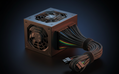
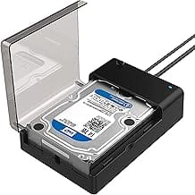
The Fuhengli 8-in-1 is a budget-tier ATX PSU tester targeting PC builders, repair technicians, and hobbyists who need a fast way to verify PSU output before or during a build. It covers the most common connector types found in ATX and SFX builds and outputs voltage readings on a 1.8-inch LCD for the main 20-pin and 24-pin ATX rails.
The standout feature is the combination of LCD voltage display and a PG (Power Good) signal indicator, which distinguishes it from passive LED-only testers. The LCD reports +3.3V, +12V1, +5V, -12V, 5VSB, and PG simultaneously when the 24-pin connector is seated, giving a real snapshot of rail health without reaching for a multimeter.
The primary trade-off is that SATA, IDE, and floppy connectors do not feed the LCD and are reported only through LED indicators, which confirm rail presence but not actual voltage values. PCIe 8-pin is explicitly unsupported despite the physical similarity to EPS 8-pin. At this tier, PSU testers are not substitutes for a proper multimeter under load, and the buzzer alarm thresholds are not user-configurable.
Buy this if you regularly bench-test PSUs during builds or repairs and want faster go/no-go confirmation than probing with a multimeter. Skip this if you need precise voltage measurements on SATA or peripheral rails, or if you are testing server PSUs with non-standard pinouts.
Connector Coverage: Supports 20-pin ATX, 24-pin ATX, EPS 8-pin, PCIe 6-pin, 4-pin ATX/P4, IDE (HDD), floppy 4-pin, and SATA connectors. PCIe 8-pin is explicitly not supported. SATA testing differentiates between 4-wire connectors (+12V, +5V) and 5-wire connectors (+12V, +5V, +3.3V) via separate LED outputs.
LCD Display: The 1.8-inch LCD is powered exclusively by the 20-pin or 24-pin ATX connector and displays +3.3V, +12V1, +5V, -12V, 5VSB, and PG signal status. PCIe 6-pin, 4-pin, and EPS 8-pin voltages are reported on the LCD as +12V2 rather than separate channels.
Fault Detection: An integrated buzzer alarm triggers when measured voltages on the main ATX rails fall outside normal operating range. Alarm thresholds are fixed and not adjustable. IDE, floppy, and SATA connector status is indicated by dedicated LEDs rather than the LCD, confirming rail presence only.
Enclosure: Aluminum alloy construction. The LCD ships with a pre-applied protective film that can be removed by the user. Enclosure material is specified as aluminum alloy for corrosion resistance and thermal conductivity, not plastic as found on competing units at this price tier.
Second most likely cause – RAM seating or CMOS battery
Modern boards are picky. A DIMM that’s 95% seated will refuse to POST, and you won’t get beeps or LEDs depending on the board. The fix is brute and reliable: push both retention clips fully open, pull each stick out, blow the slot, and press the stick back in until both clips snap closed. Don’t just nudge the clips shut with your finger, if they don’t snap from the downward pressure, the stick isn’t home yet.
If reseating doesn’t move the needle, pull every stick except one and drop it in slot A2 (second from the CPU on most boards). If it POSTs with one stick, you’ve isolated either a bad stick or a memory training hiccup. Rotate sticks through A2 one at a time to find the dead one.
Then there’s the CMOS battery. That little CR2032 coin cell keeps your BIOS settings alive, and when it dies, some boards just refuse to POST until they get fresh juice. Pop it out, check voltage with a multimeter if you’ve got one (should read 3.0V or higher), and swap in a new one. They’re three bucks at any pharmacy. While the old battery’s out, hold the power button for 30 seconds to drain residual capacitance, that’s your CMOS reset for free.
The weird one (rare but happens) – motherboard short
This one bites first-time builders and folks who’ve recently moved a rig. Motherboards mount on brass standoffs, and there’s supposed to be exactly one standoff under each mounting hole on the board. An extra standoff sitting under a spot with no hole touches a solder pad and shorts the whole system. No power, no LEDs, sometimes a brief twitch then nothing. It mimics PSU failure perfectly.
The fix is annoying but simple: pull the board, count standoffs against mounting holes, and remove any extras. While the board’s out, flip it over and look for scorch marks or discolored pads near the standoff positions. If you see burn marks, the board’s likely cooked.
Other oddballs in this tier: a stray screw that fell into the case during build and lodged against the front-panel header pins, or a CPU with bent pins. Intel pins live on the socket, AMD AM5 pins are also on the socket now (AM4 had them on the CPU itself). Pull the cooler, lift the CPU, and inspect the pad and socket under good light. Bent pins are sometimes recoverable with a sewing needle if you’re patient.
Step-by-step fix
Run this in order. Don’t skip steps because you “already know”, the whole point is ruling things out cleanly so you don’t chase ghosts.
(a) Plug a lamp into your wall outlet. If the lamp’s dead, your outlet is. Try another. (b) Confirm the PSU rocker switch is ON and the power cable is fully seated on both ends. (c) Press the power button and listen for any fan twitch, click, or relay sound. Note what you hear or don’t. (d) Open the side panel. Look for a motherboard power-good LED, most boards from 2018 onward have one, usually labeled or near the 24-pin. If it’s lit, you’ve got standby power and the PSU’s probably fine.
(e) Reseat both RAM sticks until clips snap closed on their own. (f) Reseat the 24-pin and the 8-pin CPU power connector at both ends, PSU side and board side. The 8-pin EPS is the one people forget; without it, the board won’t POST. (g) Check the PSU with a tester or paperclip method. Compare rails against spec (12V should read 11.4-12.6V, 5V should read 4.75-5.25V, 3.3V should read 3.14-3.47V). (h) If you’ve got access to a known-good PSU, swap it in. This is the fastest single check you can run. (i) If nothing’s worked, pull the motherboard out of the case and bench-check it on the cardboard box it came in. Eliminates chassis shorts in one move.
When it’s not fixable – what to replace
If your PSU tester shows rails out of spec, 12V reading 11.1V or 5V drooping below 4.7V under no load, the PSU’s done. Replace it. Budget for $70-90 for a quality 650W 80+ Gold unit for a mainstream gaming rig, or $130-180 for a 850W+ Gold/Platinum for a high-end build with a 4070 Ti or above. Don’t cheap out here; a bad PSU can take the rest of the system with it.
If the motherboard’s power-good LED never lights with a confirmed-good PSU, the board itself has failed. Plan a replacement. Match the socket to your existing CPU (LGA1700 for 12th-14th gen Intel, AM4 for older Ryzen, AM5 for current Ryzen).
CPU failure is rare but possible. If literally every component’s been swapped or checked and there’s still no life, RMA the CPU if it’s under warranty, or replace it. Also worth grabbing: a bootable repair USB for when the hardware’s fine but Windows won’t load, and a replacement front-panel power button if yours is sticky or unresponsive.

Pros
- 118-inch cable covers most under-desk or rack placements without needing a coupler or extension.
- Splitter board preserves original chassis button function while adding the external switch in parallel.
- No-drill 3M adhesive mount works on flat desk surfaces and most smooth panel materials.
- Broad ATX F_PANEL compatibility covers standard POWER SW and PLED+/- pinouts without adapter.
Cons
- Limited owner feedback at time of writing reduces confidence in long-term reliability and connector durability.
- No restart/reset function, so only power on and off are supported from the external switch.
- Adhesive mount longevity on textured or vertical surfaces is not verified by available owner data.
The LHKLUK external PC power button is a budget-tier accessory targeting builders who mount their tower in a hard-to-reach location, such as under a desk, inside a rack, or on a bare open-frame test bench. The core function is simple: extend the motherboard's F_PANEL POWER SW and PLED signals to a remote button with an LED indicator.
The defining feature is the 118-inch cable, which covers roughly ten feet of routing distance. That is enough to run from a floor-mounted tower, behind a rack panel, or through a front optical drive bay up to a desk surface. The LED indicator mirrors the PLED signal, so power state is visible even when the case itself is completely hidden from view.
The included splitter board is the most practically useful component for test-bench users. It allows the original chassis button and the external switch to both remain active, eliminating the need to choose one or the other. However, the reset/restart header is not supported, which limits utility for builders who frequently need hard resets during POST troubleshooting. Adhesive mount durability on textured or vertical surfaces is not confirmed by available source data.
Buy this if your PC case lives under a desk or inside a rack and you want push-button access at desk level without running new wiring through the wall. Skip this if you need a reset button alongside the power switch, as this product does not support that function.
Connector Compatibility: Uses a standard 4-pin F_PANEL connector wired for POWER SW+, POWER SW-, LED+, and LED-. Compatible with the JFP1 and F_PANEL headers found on ATX motherboards. Manufacturer states compatibility with approximately 90 percent of ATX boards. Not compatible with laptops or non-standard proprietary pinouts.
Cable Length: 118 inches total cable run from the motherboard header to the external switch. That equates to roughly 300 centimeters, sufficient for routing from a floor-level case to a standard desk height with slack remaining for cable management through vents or drive bays.
Splitter Board: Included 1-to-2 splitter connects to the motherboard F_PANEL header and outputs to both the original chassis button harness and the external switch cable simultaneously. Supports POWER SW and PLED signals only. Reset SW pass-through is not supported per product listing.
Mounting: 3M adhesive stickers are included for tool-free attachment to a flat desk surface or smooth panel. No drilling required. Mounting surface must be clean and flat for rated adhesion. Specific adhesive load rating is not specified in source data.
A few more questions
How do I know if my PSU is dying vs already dead?
A fully dead PSU gives you nothing: no LEDs on the board, no fan twitch, no click from the PSU itself when you hit power. Standby’s gone. A dying PSU is sneakier. Symptoms include random reboots under load (especially GPU-heavy games), USB devices dropping out, occasional failure to boot from cold but working fine after a few tries, coil whine that wasn’t there before, or a faint burnt-electronics smell from the rear vent. If you’ve got a tester, dying PSUs often show rail voltages within spec at idle but droop hard the moment load hits, that’s why bench-checking under load matters. A multimeter on the 12V rail while the system’s gaming can catch it. Another tell: the PSU fan spinning at full tilt when the system’s idle, which usually means thermal protection’s tripping early because internal components are degraded. If you’re seeing any combo of these and the unit’s older than five years, replace it before it takes the GPU or board with it. PSUs are the one component where preventive replacement pays off.
Does CMOS reset really help, or is it placebo?
It genuinely helps in a narrow set of cases: corrupted BIOS settings from a failed overclock, stuck XMP profiles that won’t POST, or after a CPU swap where the board’s confused about what’s installed. It won’t fix dead hardware. If your CMOS reset works, it was a settings problem, not a component problem.
Should I swap parts one at a time or all at once during diagnosis?
One at a time, always. If you swap three things and the system boots, you’ve learned nothing, could’ve been any of them. Change one variable, check, document, move on. Slower but it actually tells you what failed, which matters when you’re deciding what to RMA or replace.